Alarm Clock
I need an alarm clock that can help me manage various smart home features from my bedside table so that I can kick my phone out of the bedroom and get a better night’s sleep.
I’ve tried a few products, but they all have drawbacks. So I’ve decided to try to create my own using a Raspberry Pi.
Setting up & reverse-engineering the Kello display
To start on the project, I need to get my development environment up and running.
I’m used to working on frontend projects, where I can edit and run code on the same machine. But since I’m using a spare Raspberry Pi Zero W I have on hand, I’m going to be working mostly over SSH. Either that, or shell out for a mini HDMI adapter and a micro USB to USB-A hub, which won’t be relevant to the final product. Plus, it will probably be a huge plus to be able to connect to the final alarm clock at any time to update software, fix bugs, or add new features.
So to start out, I followed this guide, which worked great. Within a few minutes, I’ve got an SSH connection and I’m installing packages.
Up next, I want to be able to connect to the device and edit files from my main computer using VS Code. After reviewing a few options, I was disappointed to learn that the official Remote extensions for VS Code don’t support the ARM V6 architecture used on the Pi Zero. But, I was able to get the SSH-FS extension working as an alternative.
Putting that aside for the moment, I returned to my open SSH connection with the Pi in my terminal and installed Python 3.
sudo apt-get install python3-dev python3-venv -yNext, I’d like to be able to push my code to Git, so it’s time to install that and setup SSH access to my Github account.
sudo apt-get install git -y

ssh-keygen -t rsa -b 4096 -C ****@********
From there, I could view the generated file in VS Code using the SSH-FS extension, copy the public key, and add it to my Github account. Now I can push code from my Pi device directly to Github.
With the basics ready, it was time to define what I actually wanted to accomplish first.
Project Goals
I figure the best place to start will be the bare essentials of an alarm clock:
- Displaying the current time
- Waking me up on a schedule
That’s a good MVP. Of course, I have all sorts of ideas for Spotify integration, controlling smart lights, and telling me the weather in the morning. But for now, those things will wait.
As I look forward on how to construct the alarm clock, though, I want to play to my strengths. Here’s a few aspects of the interaction design I’m planning right now:
- The device itself will have a simple interface, either via a 7-segment display, an LED dot matrix, a monochrome OLED display, or some combination of those. If I wanted a bright, hi-res touchscreen, I’d just stick with my phone.
- The device will have a set of tactile buttons for all of the major functions which I care about when I’m in bed. Right now I can only think of a few: a. Turning off the alarm in the morning b. Turning off and on the alarm altogether c. Turning off and on the lights in my bedroom d. Maybe, activating a voice assistant (instead of hotword detection)
- For everything else, including management of alarms and other features, I’ll have the clock host a simple web interface accessible on my local network. I can connect via my phone before I go to bed to configure things if I want to change them.
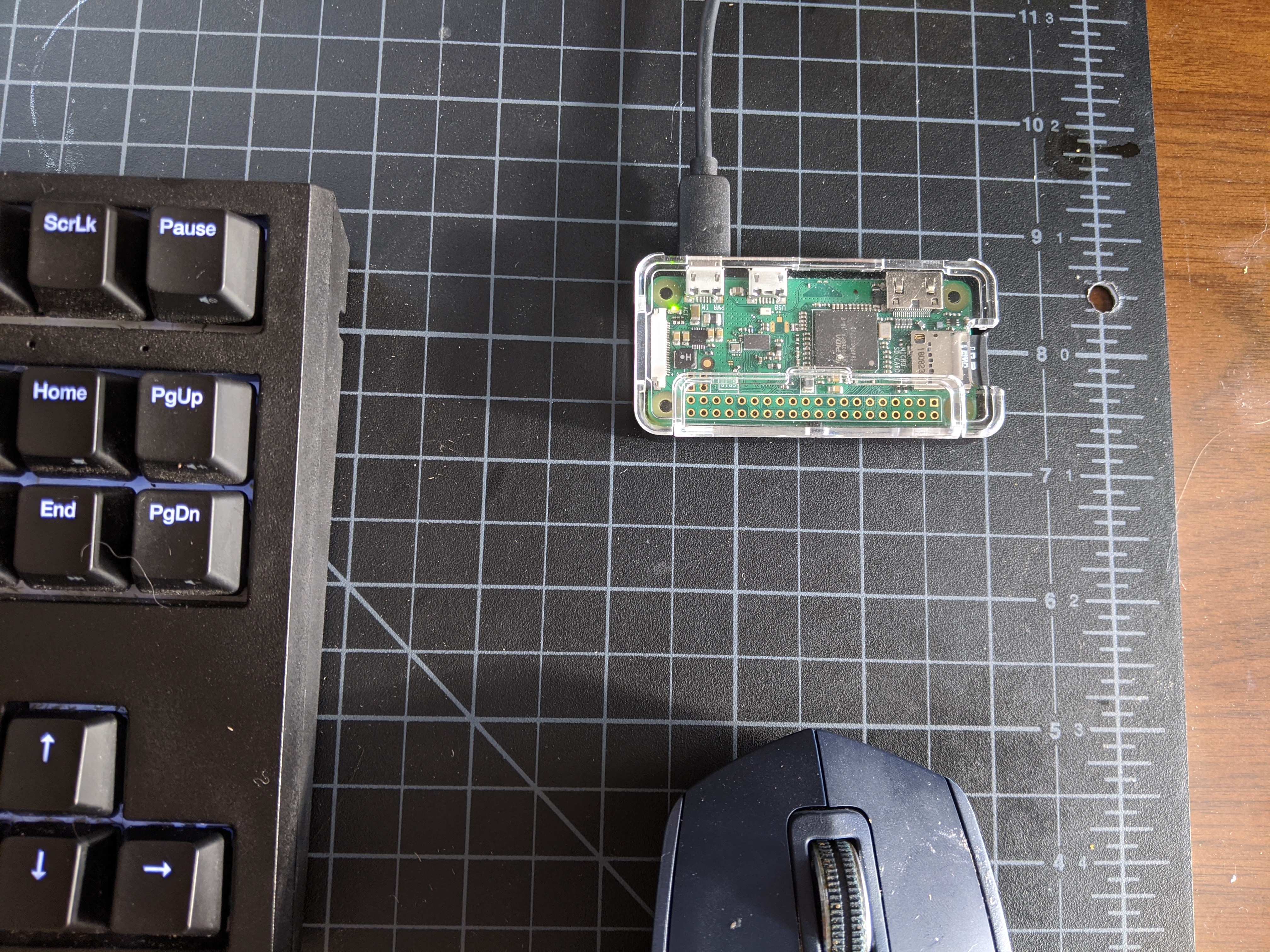 A Raspberry Pi Zero W device
Hacking the LED Matrix
Now that I’d decided on some basic features, it was time to figure out the display situation.
A few years back I first developed my interest in a smart alarm clock when I came across the Kello project on Kickstarter. I’d always wanted to be able to wake up to Spotify (I have a playlist full of Gregorian chants just for that purpose), but I also really wanted to leave my phone outside the bedroom, as I have a bad habit of getting sucked into newsfeeds in the morning instead of getting out of bed.
So I funded the project. A part of me was definitely hoping it would succeed and develop into something more mature than what launched, but that’s a rarity with things on Kickstarter I suppose. Kello delivered on what was promised, but with compromises and little further development. For one, it was kind of annoying that it didn’t connect to 5GHz Wifi, and I could never get my router to allow traffic between the 5 and 2.5 GHz networks, so I had to switch my phone’s network every time I wanted to tweak my alarms or use any of the software features in the Kello app. It was such a hassle I just stopped using the device.
Besides the limitations, though, I eventually realized what I really wanted was an alarm clock I could hack on - improving the feature set, trying new ideas for my morning routine, even just telling me whether I can bike to work each morning.
So the Kello has been sitting in the supply bin - until now.
At first, I ripped it open because I figured the speaker would be useful. But then I started shopping online for an LED display and discovered there really wasn’t anything better, or even comparable, to what the Kello offered. They’ve got 3 mini 8x8 LED matrixes with a footprint of just about 4 inches. It’s enough space to write a simple word or two, but small enough for a reasonable device profile. Everything I found online was either too little real estate, too large, or some variant of 7-segment which wouldn’t let me do alphabet characters very easily or legibly. My heart got set on the display which I ripped out of the Kello.
There was good news and bad news. The good news was, the LED matrixes were already conveniently rigged up on a discrete board which connected to the mainboard on the Kello via a 10-pin ribbon cable. That told me they had an LED driver on-board, which would be a huge shortcut on a lot of research and work for me. I kind of don’t like soldering, and I’d like to avoid printing my own PCB.
The bad news was I had no idea how they were communicating with this board or how I could mimic it.
Blind flailing
So the hard part began - I pulled the pins out of the plug connector on one end of the ribbon cable, fastened them onto a line of jumpers on my breadboard, and started playing around. I really didn’t know what I was doing.
After a bit of running power to random things (probably not a great idea in retrospect), all I’d managed to do was get the chip on the board really hot. I decided to hold off on the experimentation and do a little research.
That hot chip was a HT1632C, an LED driver chip with onboard memory for storing the current display pattern, and it could communicate via SPI over 4 pins. That was a start! I read over the datasheet, but as a software developer I was starting to feel overwhelmed. There’s a lot I don’t know.
Luckily, just searching for the name of the chip surfaced some existing code which claimed to interface. Of course, nobody was using a board quite like the one I pulled out of the Kello. After at least getting the code running on my Pi, I now had the difficult task of determining which of the 10 wires did what.
With 4 pins to drive the LED controller, plus 2 for power and ground, I figured there was a chance I could brute-force it. Several hours later, I gave up on that.
In my defense, the Kello engineers made the very strange choice of making one of the 10 wires red - which I figured was an obvious tell - but not actually using it for power input. So I spent a pretty long time swapping around wires trying to wake up a display that stayed dead, as I routed 5v power into a completely unrelated pin.
Back to the motherboard
Eventually, though, I got a little smarter. I plugged in the Kello motherboard and started reading the current it sent over the 10 pins on that end using a multimeter. At this point I discovered that the red wire was actually connected to the 10th pin, not the 1st one - a closer inspection of the board itself revealed the 1st pin was on the other end - and sure enough, when I tested the real 1st pin, it as delivering 5v power compared to a known ground. From there I basically guessed that pin 2 was ground, which checked out on the multimeter. So I basically started working from that assumption, which turned out to be a good one.
I’d like to say from there it was downhill, but it really wasn’t. I now had 8 contiguous pins to search across for the right set of 4. I wasn’t even really confident in the order of the 4 pins I would need to find. In fact, I didn’t know what the code I was using actually did, nor was I confident in how I’d mapped the pins documented in the code with the ones shown in the chip datasheet - whose names were subtly different. The software wanted CS, WR, CLK, and DATA - but the datasheet documented CS, WR, RD, and DATA. Could I assume RD = CLK?
Turns out I didn’t have to worry much about it - after inspecting the PCB design a bit more of the board itself, I came to realize the RD pin wasn’t even connected to anything. The downside was, that left me with even less information - did I need to find 4 pins or 3? What did I do with CLK? Did Kello even use SPI, or was I barking up the wrong tree?
The light at the end of the board
Having only learned about most of these things in the past 24 hours, my chances didn’t seem high of discovering the right answer through guesswork or brute forcing. Just as I was about to give up and turn back to buying a new display, though, I happened to connect a jumper from a pin on my Pi which was already set to high to position 7 on the board wiring, and there was a flash of bright red. I couldn’t believe it at first - something had actually happened!
Turns out the 7th wire in the cable is a control wire for a single LED which is mounted directly on the board, next to the matrixes. So I didn’t have any leads on the matrixes themselves, but now I could control this auxillary LED - which also proved my assumptions about the power and ground wires. I was back in business.
Although I was definitely questioning my sanity, I at least felt certain that I could get existing HT1632C code to talk to this board somehow - there weren’t any other microcontrollers on the board itself, so at some level the Kello engineers had to be sending those signals on some of the remaining 7 pins I had not discovered the purpose of - and, since humans designed the thing, I could hopefully operate on the assumption that those pins would be contiguous. But I still didn’t know whether it was 3 or 4, or what order. I wanted to narrow things down a bit further before returning to brute force.
There were still a lot of unknowns. Not to mention after so much random testing, I wasn’t even sure I hadn’t killed the HT1632C at some point. It did get really hot that one time.
Back to the motherboard, again
So I returned to detective work with the motherboard. I reassembled the original 10-pin ribbon cable connector and got all the components back together again in their original form. I crossed my fingers and powered it up - and to my relief, the display lit up. At least I hadn’t fried anything.
From there it was a matter of pulling random wires out of the harness and cycling the power on the motherboard. If the display turned on, I could assume that the wire I pulled was related to one of the other components on the board. If not, I’d hopefully found one of the control wires.
This ended up working really well! Along the way, I discovered wire 3 was somehow related to the brightness of the display - when I pulled it, the display still lit up, but very dimly. I know the Kello had a display dimming feature, so perhaps that was the control wire for that. Still not sure.
But after pulling the rest of the wires out, I could safely say that only the final 3 - 8, 9, and 10 - were responsible for the LED matrix. The rest had no effect when I removed them from the harness.
We have our suspects
Of course, with only 3 controllers, SPI seemed to be off the table. I’d need to find some new code to try. Scrolling a bit further down on Google, I happened to find zzxydg/RaspPi-ht1632c, which came to my rescue. It seems @zzxydg had likewise not had luck with SPI and taken to bit-banging over the DATA wire, and their code was beautifully documented. I made a few modifications so it would work with only 1 panel, then I loaded it up on my Pi.
And at long last - after a few iterations of rearranging my 3 control wires - there was light!
There are still a few wires which I don’t know the usage of, but I have what I need to start working on my own code to power the display. I found an NPM module that will interface with the Pi’s GPIO, so I think I’ll return to my comfort zone and write some TypeScript for the rest of the project if I’m able. Since the logic is so well-documented in @zzxydg’s library, I think I’ll be able to port it.
I have a (partial) pinout!
When all’s said and done, here’s what I now know about the pins on the Kello LED board:
1 - 5v in

2 - GND

3 - Seems to control display brightness - HIGH is bright, LOW dim

4 - ???

5 - ???

6 - ???

7 - Aux LED control, HIGH is on, LOW is off

8 - HT1632C CS (chip select) pin

9 - HT1632C DATA pin

10 - HT1632C WR (write clock) pin
This information was hard-won, and maybe it won’t be useful to anyone else. After all, I doubt too many people bought a Kello in the grand scheme of things, and of those who did probably don’t want to reuse its components. But hey, providing the information is free, so if you’re out there, I hope you find this before you spend a few long days swapping jumper wires like I did.
Next up: I’ll need to figure out how they’re mapping the unusual display size (24x8) to the HT1632C, which usually powers 24x16 or 32x8 displays. I figure they’re either using half of the former, or the first 24 rows of the latter.
And of course, actually telling time. And hooking up the speaker. And providing a web interface. I hope I’ve gotten past the worst of it!
Reorienting myself
Now that I had full confidence in my ability to communicate with the LED matrix, it was time to get more comfortable.
Python is fine, but I just prefer JavaScript, since I already spend most of my waking hours using it. And I already had Node installed on the board, so it’s just a matter of translating the working Python over to JS. I made use of the lovely node-rpio library for the GPIO.
The code translation went great, there’s really not much to the original except some bit shifting. So things were looking up - maybe I was past the headaches.
Then I tried to output some text to the display. Oops. Pictured above is my attempt at “Hello.”
It appears that the Kello engineers wired up these LED matrixes in a … unique way. Attempting to address individual columns in sequence is not going to work.
I was hoping to make this project relatively display-agnostic, maybe make it support anything HT1632C. Looks like that won’t quite be doable. In the meantime, I’m going to have to write an abstraction layer over the display addressing to fix the bizarre panel orientations. But at least the problem is pretty clear.
But hey, isn’t the display pretty? No regrets.
Display, menus, state machines
With the LED controller in place, I just needed to refine how I was putting pixels out and construct a menu system.
Turns out it was trickier than I thought - the pixels are indexed in memory very strangely! I’m not sure whether the quirks I observed were due to the way the Kello folks wired up the LED matrixes or just how the HT1632C works, but I didn’t feel like doing too much investigation this time. Instead, I resorted to old-fashioned trial and error.
Pixels are written to the display by indexing them into a stream of bits (at least, they are for me - since I’m using “bit-banging” instead of real SPI). I just have to figure out what order the bits are in, relative to X-Y coordinates that I want to work in.
To start, I just began writing an increasing number:
 Dots are turning on in the LED dot matrix - but not in the right order
So that was a bit less sensible than expected. Although the refresh rate flickering makes it a bit hard to tell, the lights are turning on in reverse order across the first panel, but they seem to be… split across the middle as well?
I was a little burnt out on thinking at this point, so I just began iterating on algorithms. Eventually, it worked. The code can’t be summarized too well in English, but here it is.
The next step was to beef up the LED driver code with a framebuffer system, so I could write multiple things on the screen virtually before flushing it to the device - the device write has a noticeable delay, so consecutive writes are best avoided.
But writing the time, while great, is just the basics. To display a system of menus which I can utilize, I need both hardware controls and logic to determine what’s on screen.
For that, I turned to XState. I’ve never used it before, but I’ve seen a lot about it! State charts are known to be less prone to logic errors, and the last thing I want is a logic error in a device I will only be using when I immediately wake up or when I’m already in bed - neither a great time to fix a bug.
Creating a state chart was fun! I enjoyed the experience of declaring the structure of the state transitions before I ever had to write implementation code. I used activities to implement drawing to the screen, which might not be the explicit intention, but did end up working just fine. Activities remind me of React’s useEffect, in that they allow the returning of a “cancel” callback. This models the loop required to draw most screens effectively pretty well - I subscribe to events to update the screen, and can unsubscribe when the state transitions.
With the code in place, I connected a rotary encoder to the Pi for control. When the encoder is turned or pressed, events are sent to the state machine.
That’s enough for now - next, it’s time for playing an alarm. Of course, it was only now that I realized the Pi Zero W doesn’t have an audio out… that’s a tomorrow problem.
Sound, and an ugly UI
Without an audio output on the board itself, it was time to go back to the internet for a new component to enable audio output from my Pi Zero W.
Thankfully, it didn’t take long to find the MAX98357 chip and learn how to output sound using I2S. This blog post got me where I needed to go, and after ordering a chip online I was soon hearing Neil Armstrong announce his achievement from the speaker I ripped out of the Kello. It is, indeed, a pretty nice speaker.
There remains the question of how I’m going to set up this Pi as a Spotify Connect target so I can stream music to it in the morning, but I’ve at least got a lead on some open source solutions for that.
So now pretty much all the hardware I need is set up: I have my display, my control, and my speaker. I can start thinking about the final housing design and how to arrange components pretty soon here.
But for the immediate future, I’ve decided to flesh out the web interface. As part of my objective of keeping the physical interface of the device extremely minimal, I wanted to have the clock host a simple web dashboard only local network which I could access from a phone or laptop to tweak my alarm schedule or change the Spotify playlist.
I know a full-blown React app is probably overkill for this, and maybe I should branch out a bit. But the truth is, I’m so comfortable with React as a tool that I figure I’ll have a better chance of success if I stick with it this time. I’ve already learned quite a bit on this project, and I’m likely to learn quite a bit more as I wrap it up - so it’s nice to chill out with some stuff that’s not so challenging in the middle. If I push things too hard, I may end up burning out on the project, and I really do want to end up with a working alarm clock.
Now one of the big problems with React is that it requires transpilation. I actually abandoned TypeScript in the previous code because transpiling it directly on the Pi is just too much. Basic Babel for React is no different. After sitting and waiting for Webpack to finish recompiling for upwards of 10 minutes, I decided to move my development back onto my main computer. I can still have the development frontend talk to the Pi’s server over the local network for now, but I’ll probably want to flesh this out into a more coherent developer environment. That means either figuring out a way to compile code on my main computer and copy it via SSH to the Pi in realtime, or creating a simulator for my clock hardware that I can plug in so I can run the whole thing locally. Both are interesting options.
For now, I have a really ugly UI that can modify alarm schedules. That’s all I feel like doing today.
Spotify!
The core features are finally coming together. With the hardware more or less complete, the rest is going to revolve around software and integration with various services - starting with Spotify.
To begin, I needed to make my Raspberry Pi a Spotify Connect target so I can play music to it. Thankfully, that was really easy! I just run a Raspotify daemon on the device and it shows up in the app like magic.
It took a bit of thinking to figure out how I was going to get this to work as an alarm clock, though. After all, there’s nothing on the Pi itself that allows it to control when media is played or what’s playing. I started looking more at Spotify’s developer documentation and quickly came to the conclusion that I’ll also need to incorporate the Spotify API into my clock’s core server.
Using the API, I can have the clock call out to Spotify and tell it to play a particular playlist on a particular device (this one) in the morning.
Of course, to properly login with Spotify I have to implement a standard OAuth 2.0 flow on my little server running on the Pi. Luckily I’ve done this flow a few times now, so while it’s a bit confusing at first, it didn’t take long to get things going. In fact, the biggest thing I got stuck on was trying to figure out how to send a form-encoded request in Node… it’s the little things I guess.
For now, I’m just storing the refresh token on the device, which seems like it will work fine. I abstracted the same persistence layer I already had in place for the main clock settings into a reusable class which I’m quite pleased with. It caches the stored values when you set them, so it doesn’t hit the disk too much. And it’s an event emitter, so you can subscribe to changes.
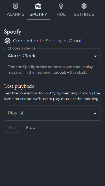
A few API proxy endpoints later, and I can select a playlist to use on a particular morning:
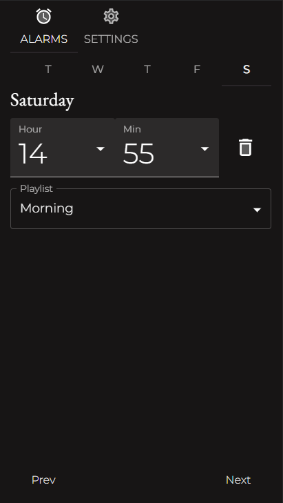 Alarm clock UI
I’m quite happy with my progress on the software side. The UI is looking a bit more professional, and Spotify integration was one of the bigger hurdles I anticipated when it came to the settings configuration.
Perhaps tomorrow or next week I can wrap up the music part by triggering Spotify to actually play something when the alarm is fired. At which point… this is actually an alarm clock!
Spotify alarm, Hue integration
There’s still a lot of software to write… the good news is, it’s kinda fun! It’s like a world tour of smart home APIs. I guess I always knew it was theoretically possible to connect to all these services, but it’s been cool to actually do it.
Today I rounded off the Spotify aspect, making it so the Pi can switch the active device to itself in Spotify and then start a playlist chosen by the user.
Since that worked so well, I felt like taking a victory lap and setting up Hue. After grabbing a module from NPM, this also proved pretty simple. I enjoyed figuring out the whole “push button to connect” aspect with the Hue bridge and what goes on behind the scenes.
Not too much to say about this update, I guess. I can now set an alarm and it will play a playlist. I can also turn on and off the lights in my bedroom using the rotary encoder menu on the clock itself.
At some point soon I’ll really have to create a housing for this thing so I can start using it - it should already be functional!
 Alarm clock UI
Setbacks with Spotify
It was starting to look like Spotify is going to be less of a robust option.
The main problem I was experiencing was that, while the Raspberry Pi is listed as available when I query devices from the Spotify app directly, the Spotify service seems to kind of… forget about it. After a few hours, the device is no longer listed when I query via the API. That didn’t bode well for the alarm clock being controlled in the morning.
While integrating with Spotify was fun, I was starting to come to terms with dropping the functionality. I already have a good bit of Gregorian chants on MP3 which I could play directly from the device, which would save a lot of hassle.
However, I noticed there was a configuration option for Raspotify which allows passing in Spotify credentials directly. Perhaps using this it would create a more persistent connection.
Having done that, I’ll have to wait and see if the device gets forgotten again. Obviously none of this is official Spotify stuff, so what I’m trying to do may just not be possible unless I become a Spotify hardware partner (unlikely).
The Kello solved this, apparently, using a specific hardware chip which I located on their motherboard. It’s from a company called Libre. It appears this chip acts as a separate microcontroller and handles everything related to Spotify streaming, including registering a Connect device and presumably keeping that connection alive.
However, the device has, if I count correctly, 60 pins. I’m just not ready to try to figure out how to interface with it. It’s not worthwhile.
So if this new authenticated Respotify option works, cool, but if not… playing MP3s isn’t so bad. I went ahead and coded the functionality to play MP3s directly and made it the fallback in case the Spotify connection doesn’t work in the morning, so I feel pretty good about it.
On the hardware side, I ordered some parts I’ll need to assemble a final prototype board, and I’ve mocked up an enclosure by slicing up an old Amazon box. I’m pretty happy with the form factor, and the components all fit inside. I’m a little worried about the speaker now though, since it’s been kind of buzzy…
Knob and brightness
Maybe one day I’ll go back and come up with more clever titles for these posts.
I took a little break from the project while I waited for a few parts to come in which I would need to assemble a final perfboard. For one, I needed some screw-down terminal blocks to properly rig up the ribbon cable which I destroyed in order to interface with the Kello display module. The cable used incredibly thin stranded lines, so there wasn’t much hope of soldering them effectively with my skills.
I also ordered a nice shiny aluminum knob for the rotary encoder. Originally I had a mind to try to mill my own knob out of wood, but I think trying to learn woodworking in addition to the rest of the challenges would have put my perseverance on this project to the test. The last 20% is always 80% of the effort, as a rule of thumb, and I don’t need to add any more hurdles to that. Plus, the aluminum is a pretty nice accent and looks professional. It might actually be the nicest looking part of the final product.
Before I started soldering, though, I wanted to make sure I had gotten everything I wanted out of the hardware. The final thing I’d been ignoring was display brightness.
Making sure the display isn’t obnoxiously bright is important enough to spend some time on. This thing will be sitting right next to my face while I’m trying to sleep, after all. I want to make sure I can control it through software so that I can tweak the settings as needed without opening up the casing or having to make modifications to the wiring.
The biggest question I needed to solve revolved around the 4th pin on the display cable. I’d noticed when testing that if I run power to that line, the display becomes brighter. 3v is suitably bright, 5v is bright enough to be clearly readable in full light. But I didn’t really have a software method to control the voltage I’m supplying to that pin, and I wasn’t even really sure that was the right way to do this.
For a while I mulled over purchasing some step-up level shifters and attempting to adjust the power on that pin by creating a 5v PWM signal. But that seemed pretty complicated for something which should, in theory, be simple - Kello was able to finely tune the brightness on the display, and surely they weren’t resorting to this kind of hack. I figured I was missing something.
So I took a trip back to the datasheet for the HT1632C. And what do you know, turns out the chip has a built-in PWM for brightness! Reading the instructions a little more closely, I saw that all I need to do is send a specific command for the brightness level, 1-16. Which means the 4th pin must simply be a second 5v power line that I can wire up permanently. I had found my fix.
With that, I feel pretty confident to begin assembling the final board.
Perfboard soldered, plus uh… prototype casing
It’s been a long time coming - I finally ditched the breadboard!
Today the solid-core wires I ordered (when I realized my last shipment contained stranded - oops) finally arrived, and I was able to complete the perfboard design I diagrammed and assemble the first complete prototype.
Things went off mostly without a hitch - I did accidentally get the wrong pin for one of the speaker inputs, but was able to figure it out and bodge it with a solder bridge.
After some final alarm functionality testing and bug fixes, I’m ready to put it on my nightstand and begin using it as my daily wake-up device! My phone will sit beside it for now… I’m not sure I trust it completely.
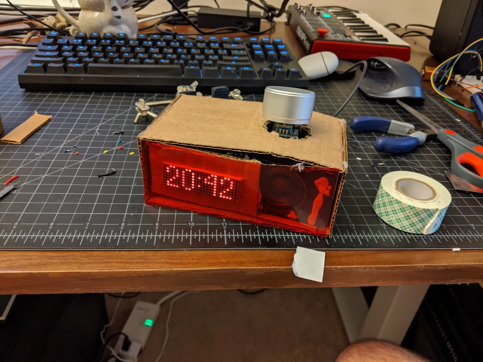 An ugly cardboard enclosure prototype for the alarm clock
The cardboard housing is… inelegant. But the ugliness of it may at least help motivate me to see this through to the end, with a real housing. I’m hoping to make something out of wood.
I guess I’ll see how I feel about this achievement tomorrow morning - but for now I feel great!
Assembled: v1
After a bit of testing with the prototype casing, I’m finally ready to assemble a more permanent housing - using LEGO.
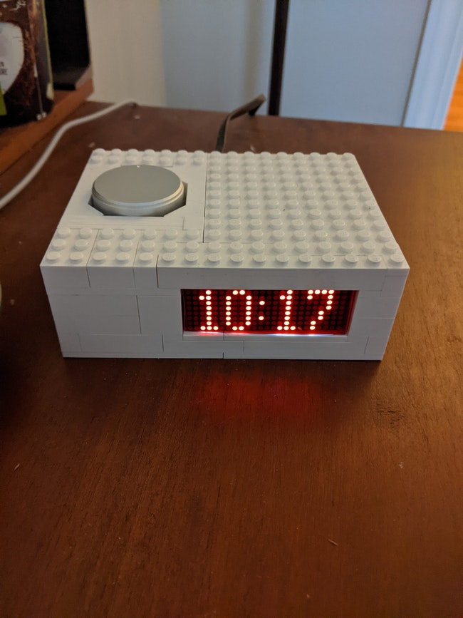
LEGO turns out to be a great option for this kind of thing, if you don’t have a 3D printer or woodworking skills.